How To Test A Motherboard
How To Test A Motherboard
In my 30 years as a computer technician, I've found that a motherboard is one of the most difficult components to diagnose due to the sheer quantity of components attached to it.
If your motherboard breaks, you may experience blue screens, freezing, beeping, and the inability to detect USB devices and other hardware, among other symptoms. This post will teach you how to visually inspect, troubleshoot, and test your motherboard for problems using a multimeter.
Necessary Tools
To accomplish your motherboard diagnostics testing, you will require the following tools.
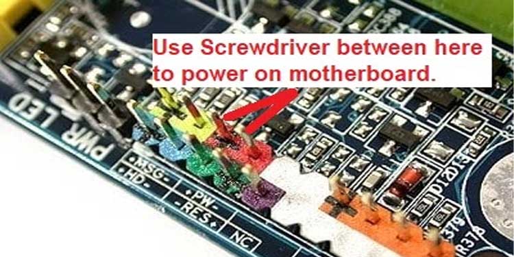
- A Phillips screwdriver or a jumper wire for the power switch
- A multimeter for measuring voltages
- A functional power supply unit (Power Supply Unit)
- If necessary, a new CMOS battery
- Thermal paste for the CPU
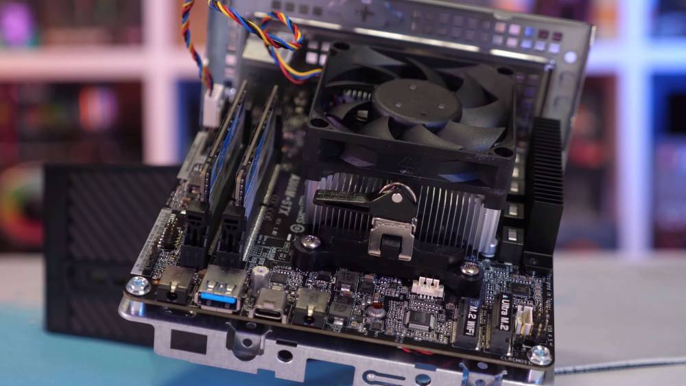
How To Test A New Motherboard
Prior to installing your fresh new motherboard into the case, you must POST (Power-On-Self-Test) the motherboard to ensure that it functions properly and that you did not receive a DOA motherboard (Dead On Arrival).
- Place the motherboard on a non-conductive, flat surface, such as a wood table.
- Install the processor and coat the heat sink with thermal paste.
- Connect the CPU cooler to the motherboard.
- Insert at least one RAM module into the corresponding slot (DIMM 1).
- Connect the GPU to the motherboard and, if necessary, the relevant power connector. Verify by consulting your GPU's handbook.
- Connect the ATX 24-pin connector from the power supply to the motherboard via the ATX 24-pin connector.
- Connect the monitor to the HDMI port on the board's side for onboard graphics or to the GPU if it will be your primary display.
- Connect the power supply unit's power wire to a surge protector or wall socket.
- To power on the computer, use a power switch jumper or, if none are available, complete the power circuit illustrated above with a screwdriver.
- After verifying a successful POST, power down the PC by resetting the power supply's power switch to the off position.
You are ready to go if the machine boots to the BIOS. Unplug everything and reinstall the motherboard into your case, following the manufacturer's instructions. If your motherboard does not POST, repeat the instructions; if that does not work, contact the motherboard manufacturer to obtain an RMA for a replacement motherboard.
How To Diagnose Motherboard Failures
Due to the sheer amount of microscopic components embedded in motherboards, they might be one of the most difficult components to diagnose. Typically, when motherboards fail, they will not boot, power on, or do anything else. The steps below can assist you in narrowing down your symptoms.
- Each time you switch on your computer, the Power-On-Self-Test, or (POST), occurs. If your machine is functioning normally, you should proceed with the startup procedure. Proceed to the next step if you are unable to complete the POST.
- Inspect your case to ensure that your motherboard is not shorted out. Ascertain that stand-off screws have been fitted accurately in all of the case's screw sites.
- Perform a temperature check on your system to rule out any possibility of overheating. Open the case and check for dust accumulation on the fans, components, and motherboard. If so, clean it with a can of compressed air from your local hardware shop.
- While launching your computer, listen for beep codes. These beep codes will assist you in determining the malfunctioning component or issue. To view a list of beep codes and their associated meanings, go here.
- Utilize the BIOS to check for, download, and install updates. If no updates are available, restore or reset your BIOS to its factory default settings and restart the machine.
- If you continue to be unable to access the BIOS as a result of your computer restarting, replace the CMOS Battery. If your PC enters BIOS following battery change, your motherboard problems should be resolved. However, if they do not, continue with the diagnostic.
- Finally, unplug everything except the CPU, the CPU Cooling Fan, and the RAM. If your motherboard boots and POSTs normally, you must add hardware one piece at a time until you locate the defective component.
How To Test A Motherboard With A Multimeter
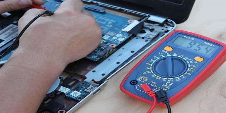
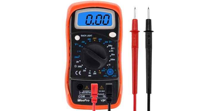
If the techniques outlined above are unable to diagnose your motherboard, it is time to utilize a multimeter. One can be purchased at a hardware store or on Amazon. This one is cheaper than $13 on Amazon and works perfectly.
If you have a multimeter, you can easily discover motherboard problems. Even if you've never used a multimeter before, I'll show you how to test your motherboard for component failure step by step.
How To Check Ac Voltage
With the multimeter, the first thing you want to look for is a short circuit. These are frequent problems that can occur during a power surge. The following section will verify the motherboard's ac voltage.
- Switch off the computer and disconnect all wires.
- Allow around ten minutes for everything to cool and lose its charge.
- Adjust the multimeter to the lowest setting possible. Resistance of (0.1) or 200 (OHMS).
- Reset the meter to zero by touching both leads together, then contacting the chassis to confirm that you still get a 0.
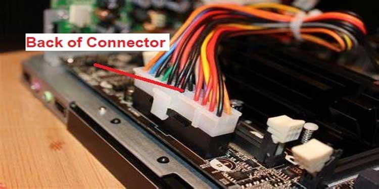
- Open your computer and locate and remove the ATX power connector on the motherboard.
- Connect the red lead to the ground pin of the power connector (any black wires) while also connecting it to the chassis's black lead. You should still have a reading of 0 in this case.
- Leave the black lead connected to the chassis and examine all colored wires using the red lead. Ascertain that each voltage is correct in accordance with the pinout below. It is acceptable if the voltage is little higher. If it is below, there is an issue.
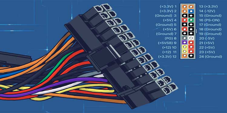
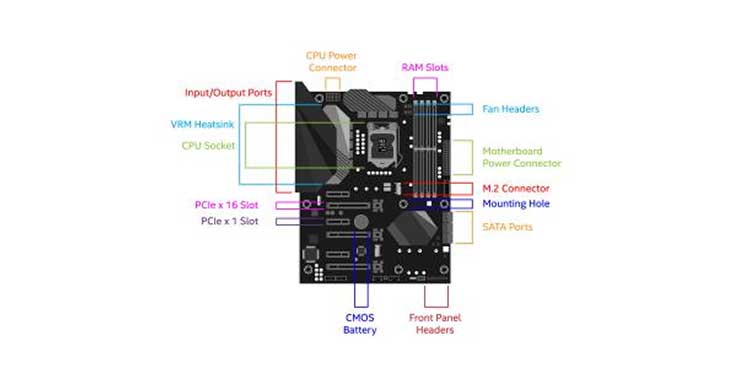
- Next, remove the motherboard from the case and locate the PINs using the layout image or this ATX 24-pin chart. Test each of the following with the red lead: (3,5,7,15,17,18, and 19) must have a 0 reading. Anything else is indicative of a faulty power supply hookup.
- For the final test, you will need to unplug the ATX power adapter and CPU from the motherboard. Analyze the identical ATX pins on the motherboard. Any value different than zero indicates that there is an issue with the motherboard connector.
How to check DC Voltage
The procedures below will demonstrate how to check DC voltages. The stages are slightly different in this case than with AC voltages.
- Connect the 24-pin ATX cable to the motherboard and then the power supply unit to a wall outlet.
- Set your multimeter to 20V DC.
- Using the black leads, probe the connector on the rear, making contact with pins 17, 18, and 19.
- With the red lead, probe pin 9 (which should read 5V) and then pin 16. (should read between 3-5V).
- Now turn on the computer; if the readings go to zero, that is fantastic. Otherwise, you'll need to replace the motherboard.
- Check pin 8 with the red lead once again. It should read little higher than 2.5V. Press the reset button on your computer to see whether the values decrease to zero and then return to normal. Otherwise, the motherboard will need to be replaced.
If you discover that your motherboard has failed, do not attempt to repair it yourself. Even if a repair is successful, incorrect voltage management may cause your computer to crash. It is usually preferable to have an expert electronic technician repair or replace the motherboard rather than attempt to do so yourself.
How To Test RAM Slots On Motherboard
- Using the black lead, probe the rear of the connector carefully while the computer is turned off. It should be connected to one of the negative pins 15,17,18, or 19, indicating a zero voltage.
- Using the red lead, probe and test the following pins: Pin 16 (green color), which should read between 3-5 volts, and Pin 9, which should read 5 volts.
- Now, restart the computer. Pin 16 (green) should be brought down to zero volts. If not, this indicates a malfunctioning switch. (Power down the computer)
- Finally, connect the red lead to Pin 8 (gray color) and check for a reading of 5 volts. Once the computer is started and the reset button is pressed, the voltage will decrease to 0 volts and then return to 5 volts. Otherwise, this is a good indication that you have a bad RAM slot and will require a new motherboard.